Tuesday, January 18, 2011

PIC Uart to PC's Serial Port Communication Circuit

This is a simple circuit for communicating PIC to PC's Serial Port

It uses a hardware UART of PIC16f628a. A level converter used is a max232 chip.

Please refer to the datasheet of both IC to check its vcc and ground pins.

Here's the schematic:

Simple Analog Comparator Circuit using lm311

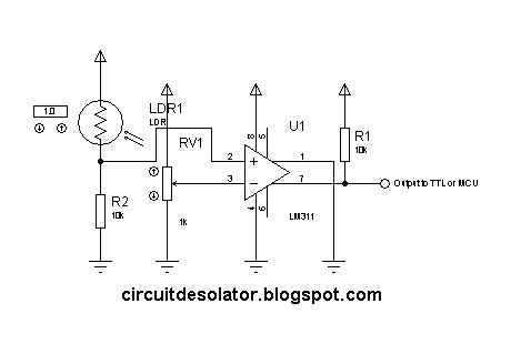
This is one of the common circuit blocks being used both in digital and analog electronics. Its output is dependent on the relationship of its two input pins. One of the inputs is set to give the reference voltage while the other one is commonly connected to different sensors. If the reference voltage was overcome by the input connected to the sensor, the output of the comparator changes.

In this circuit, the we'll use an LDR.


The advantage of a comparator IC than an opamp used as an comparator is the property of IC comparators to be open collector output. Having this feature, we can set the output of the comparator beyond its biased voltage.

Traffic Light Circuit (based on 4017)

This is a simple design of a traffic light project that uses 4017 IC. This circuit demonstrate a simple two traffic light. 

The clock source is not included in the diagram but you can use 555 astable circuit as an oscillator.

The time of switching of the lights are in proportions.

3/10 for green
2/10 for yellow 
5/10 for stop


In the schematic, a traffic light model was used in the simulation. But in the actual, you can implement it using LEDs.

Here is the schematic of the traffic light circuit:


This is a demo video:


Saturday, January 15, 2011

Latching Relay Circuit

There are situations that we need to implement latching relay action. This can be implemented by connecting the relay pins to proper configuration with respect to the button and the power source. In this blog post, I will present the circuit/schematic and demo video simulation of a latching relay.

Here is the schematic:


The components in this circuit are:

1. 1 latching switch --> serves as the reset
2. 1 normally open switch --> acts as the trigger button
3. 1 diode(1n4001) --> snubber diode against kick voltage
4. 1 spdt 5v relay
5. 1 LED --> serves as the load
6. 1 330 ohm resistor --> current limiting

**The power source is operating in 5volts.

The circuit can also be triggered by logic ICs(TTL/CMOS) using proper interfacing method. I usually use another relay that serve as the trigger button when interfacing ICs to latching relay circuit.

Here is the demo video:


Wednesday, January 12, 2011

Simple Light or Dark Activated Switch Circuit

This is a basic circuit that can be constructed by students.

It uses a transistor as a switch, LDR as the sensor, variable resistor for calibration, diode as a snubber and the relay as the switching component.

Sunday, January 9, 2011

PIC based PS/2 AT Keyboard Decoder

I constructed a simple PIC based PS/2 AT Keyboard Decoder that is frequently used as an input device to different electronic projects.

Thursday, January 6, 2011

Simple utility amplifier (using LM386)

Simple amplifiers are easy to build. Specially if you're using amplifier ICs.

Here is my simple utility amplifier. I used this on project development, etc.

This is not an advisable design but enough if you just want to hear louder sound from you coming input.


Here is the schematic.

Sunday, January 2, 2011

3-bit JK Down Counter Circuit

JK flip-flop is commonly used in different counter circuits.

This is a circuit of a 3-bit JK down counter circuit.

Note that the push button needs a switch debouncer to have a clear count. Click here on how to implement switch debouncer.

Demo video using Proteus Isis 7 (Download proteus here)

Basic led chaser circuit (4017)

This is a simple demo of a led chaser using 4017. It has an enable, reset and cascade pin making it a good choice in logic circuit design.

Please note that the schematic doesn't contain the oscillator circuit and the V+ and GND of 4017 are hidden.


Here is a simulation video of the Led chaser using Proteus Isis 7(Download proteus here)


Saturday, January 1, 2011

Logic Based Digital Queuing System Circuit (74192 counter)

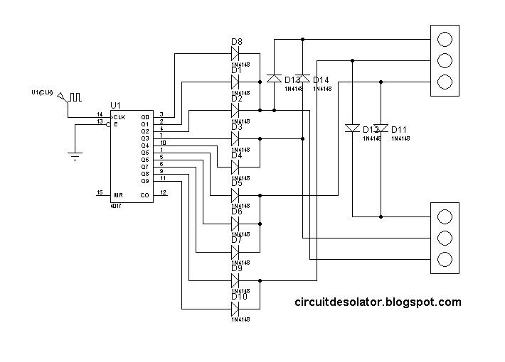
Another common logic circuit project is an electronic queuing system.

This is a simplified design using a up/down counter IC, 74192. It is a versatile logic IC that has a separate pins for up and down count. Also, an RS latch is used for the indicator of the counter number.

Here is the schematic/circuit design.


Please note:
1. Check the V+ and GND of the IC used. They are hidden on the schematic.
2. The seven-segment display needs current limiting resistor.
3. Switch debouncer circuit might be need if switch bounces are present. A reference on switch debouncer(Click Here).


Simulation video using Proteus Isis 7(Download proteus here):


Logic Based Digital Queuing System (74192 counter)