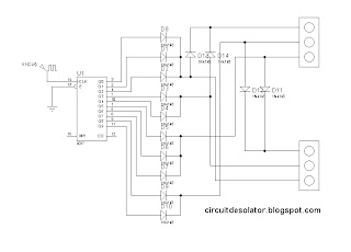
This is a simple design of a traffic light project that uses 4017 IC. This circuit demonstrate a simple two traffic light.
The clock source is not included in the diagram but you can use 555 astable circuit as an oscillator.
The time of switching of the lights are in proportions.
3/10 for green
2/10 for yellow
5/10 for stop
In the schematic, a traffic light model was used in the simulation. But in the actual, you can implement it using LEDs.
Here is the schematic of the traffic light circuit:
This is a demo video:

3 comments:
hi, what is software that u use to simulate your digital circuit?
hello
can you tell me what i can use in place of clock pulse. by circuit of 555 lights glow very fast.
Please can you tell me why did we use diodes and why did we connect them like this, to another diode and to red or green?..... Explanation please
Post a Comment