Showing posts with label Logic Circuits. Show all posts

Tuesday, January 18, 2011

Traffic Light Circuit (based on 4017)

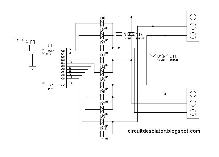
This is a simple design of a traffic light project that uses 4017 IC. This circuit demonstrate a simple two traffic light. 

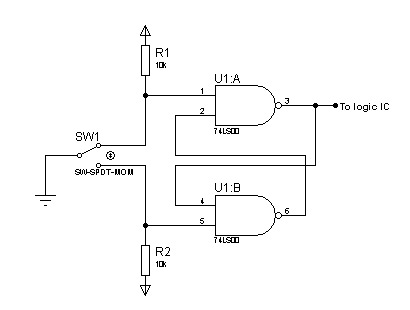
The clock source is not included in the diagram but you can use 555 astable circuit as an oscillator.

The time of switching of the lights are in proportions.

3/10 for green
2/10 for yellow 
5/10 for stop


In the schematic, a traffic light model was used in the simulation. But in the actual, you can implement it using LEDs.

Here is the schematic of the traffic light circuit:


This is a demo video:


Sunday, January 2, 2011

3-bit JK Down Counter Circuit

JK flip-flop is commonly used in different counter circuits.

This is a circuit of a 3-bit JK down counter circuit.

Note that the push button needs a switch debouncer to have a clear count. Click here on how to implement switch debouncer.

Demo video using Proteus Isis 7 (Download proteus here)

Basic led chaser circuit (4017)

This is a simple demo of a led chaser using 4017. It has an enable, reset and cascade pin making it a good choice in logic circuit design.

Please note that the schematic doesn't contain the oscillator circuit and the V+ and GND of 4017 are hidden.


Here is a simulation video of the Led chaser using Proteus Isis 7(Download proteus here)


Saturday, January 1, 2011

Logic Based Digital Queuing System Circuit (74192 counter)

Another common logic circuit project is an electronic queuing system.

This is a simplified design using a up/down counter IC, 74192. It is a versatile logic IC that has a separate pins for up and down count. Also, an RS latch is used for the indicator of the counter number.

Here is the schematic/circuit design.


Please note:
1. Check the V+ and GND of the IC used. They are hidden on the schematic.
2. The seven-segment display needs current limiting resistor.
3. Switch debouncer circuit might be need if switch bounces are present. A reference on switch debouncer(Click Here).


Simulation video using Proteus Isis 7(Download proteus here):


Logic Based Digital Queuing System (74192 counter)

Thursday, December 30, 2010

Digital Clock based on 74ls90

Digital clock never get obsolete on digital electronic projects.

Many approach and design are available online but implementing it using 7490 decade counter is one of the easiest design. This can be proven by looking at its simplicity and compactness.

Check its datasheet to see it's pin configuration and how it's being implemented.

On our digital clock circuit. We will use divide-by 10, divide-by 6 and divide-by 2. This circuit design is not adjustable so you need to start the clock exactly 00:00 or 12am.

here's the circuit of 7490 to be used:

for SECONDS' ones, MINUTES' ones and HOURS' ones are divide by 10.

for SECONDS' tens and MINUTES' tens are divide by 6.

for HOURS' ones is divide by 2.

please refer to the diagram below for the appropriate circuit.


The output of the HOURS' tens digit is connected to an AND gate that will reset the counter to 00 when 12 is counted.

The clock source will depend on the designer. It can be a 60hz from the powerline, 555 astable mode, crystal oscillator or any oscillators.

here's the circuit:


Here's the simulation video using Proteus Isis 7 (Download proteus here):


Up/Down Counter Circuit

Counters are very common experiments on digital electronics subjects.

Here's a simple up/down counter that uses 74190.


This circuit is easy to implement and here are some of its features:

Presettable - having this capability, it is easy to use for down timers with initial value like 24second shot clock.
Parallel output(BCD) - its bcd output can be easily interface to a bcd-to-sevensegment decoders.
Ripple clock output - you can cascade many 74190 to form 2digit, 4digit and Xdigit counters.
Single input pin for up/down - in case that the requirement is to control the count in a single pin, this 74190 is very applicable.

Please note that you need a switch debouncer on the switch so that you can have a clean count..

Reference for switch debouncer.
http://circuitdesolator.blogspot.com/2010/12/switch-debounce-circuit.html


Simple magnitude comparator (7485 IC) Circuit

In designing logic circuit, it is sometimes necessary to compare values of two digital data. In this case, creating your own magnitude comparator can cause you more logic IC and can consume more time and money. This magnitude comparator IC might help you. It can compare two 4-bit data but can be cascaded to other magnitude comparator. It is the 7485 IC.

This 7485 magnitude comparator is one of my favorite logic ICs. This IC helped me a lot in my school projects specially on digital electronic games like chess, fight combat, etc. I usually use this chip in declaring the winner of having a higher score.

Here is a sample circuit.


A demo video of the magnitude comparator simulation using Proteus Isis 7 (Download Proteus here)


Tuesday, December 28, 2010

Pull-up and Pull-Down Resistor

Most of the beginners in digital electronics assume that the hanging input is a logic 0. Then, that's a misconception. They are neutral state which can be a logic 0 or a logic 1. This will bring chaos on your circuit operation.

To solve this problem, we add a pull-up and a pull-down resistor.

Below is an image of pull-up and a pull-down.


As you can see, in each case there is a default input. For a pull-up, the default input to the logic IC is 1. And for the pull-down, the logic is 0. The resistor also provide a current limiting function thus affecting power consumption of the input section. 10kohms is the commonly value but any value can be use depending on your application.

Switch debounce circuit..

 In most digital electronics projects that uses different kinds of switches, switch bounces are commonly encountered. These are extra glitches after the real switch operation. These are tiny pulses that affect the actual operation of the circuit like counters.

Here's a demo video of a switch bounce.


It is clearly seen that in certain push on the switch, the counting is not accurate. This is causee by the switch bounce. Here now is the image that shows switch bounces and a clean pulse.


As you can see in the top image, this is an image of a clean pulse without a switch bounce. On the other hand, below it, shows the bounces formed from switching.

The upper image use a circuit that is called switch debounce. A switch debounce can be software or hardware. We will create the latter.

The circuit below is a RS latch that is used as a switch debouncer. It's composed by two 2-input NAND gates with outputs feedbacks to the input of another. (other explation from malvino)


Here is now a video of a counter with swich debouncer.