Saturday, December 22, 2018

Installing Anaconda Distribution and OpenCV in Windows PC

I am doing lots of Image Processing projects based on OPENCV and Python. This is how to setup it up on a Windows PC.
You need to download Anaconda and OpenCV.

OpenCV download link:

https://sourceforge.net/projects/opencvlibrary/

The version I have on my machine is 3.2.0. Executable file is "opencv-3.2.0-vc14.exe".

Anaconda download link:
https://www.anaconda.com/download/

For the Anaconda, I still use Python 2.
The version I have on my machine is 4.4.0. Executable file is "Anaconda2-4.4.0-Windows-x86_64.exe"

You need to install Anaconda. After installation you will have access with the default IDE which is Spyder. I have a stream.py script when I captured my screen.

It is now time to install OpenCV.

Put the .exe installer to the C: drive and install it. You will have an opencv folder after installation.


Next step is to copy-paste cv2.pyd file to Anaconda Site-packages to be able to import it to our Python scripts.

The location of cv2.pyd file is located here:

For 64bit machines (C:\opencv\build\python\2.7\x64)
For 32bit machiens (C:\opencv\build\python\2.7\x86)

Paste it on this location. (C:\ProgramData\Anaconda2\Lib\site-packages)

You should be able to import cv2 on a python script.

On the Spyder console on the lower right part. I use IPython console.

Try to input import cv2.


Then check version by print cv2.__version__.

You can now try to access the webcam on your laptop or PC.


import cv2, time

cap = cv2.VideoCapture(0)

while(True):

    ret, frame = cap.read()
    print ret
    if ret == 1:
        cv2.imshow('frame',frame)
    else:
        print "no video"
    if cv2.waitKey(1) & 0xFF == ord('q'):
        break

cap.release()
cv2.destroyAllWindows()


You can also access IP cameras.

cap = cv2.VideoCapture("http://192.168.1.7:8080")

And also input video files.

cap = cv2.VideoCapture("test.mp4")

Wednesday, July 10, 2013

Programming ATMEGA328-AU and other non-P type on Arduino using USBasp.

I am searching for the fix on programming ATMEGA328-AU on arduino board using USBasp. It turns out that I need to modify avrdude.conf file to much the signature. This link present the solution.


This is the error I get,

avrdude: Expected signature for ATMEGA328P is 1E 95 0F Double check chip, or use -F to override this check.

To fix this, I as metioned on the above link, I need to modify the avrdude.conf file located here,

C:\Program Files\Arduino\hardware\tools\avr\etc

I need to modify the signature entry of ATMEGA328P from,

#------------------------------------------------------------
# ATmega328P
#------------------------------------------------------------
part
    id = "m328p";
    desc = "ATMEGA328P";
    has_debugwire = yes;
    flash_instr = 0xB6, 0x01, 0x11;
    eeprom_instr = 0xBD, 0xF2, 0xBD, 0xE1, 0xBB, 0xCF, 0xB4, 0x00,
 0xBE, 0x01, 0xB6, 0x01, 0xBC, 0x00, 0xBB, 0xBF,
 0x99, 0xF9, 0xBB, 0xAF;
    stk500_devcode = 0x86;
    # avr910_devcode = 0x;
    signature = 0x1e 0x95 0x0F;
    pagel = 0xd7;
    bs2 = 0xc2;
    chip_erase_delay = 9000;
    pgm_enable = "1 0 1 0 1 1 0 0 0 1 0 1 0 0 1 1",
"x x x x x x x x x x x x x x x x";

 to,

#------------------------------------------------------------
# ATmega328P
#------------------------------------------------------------
part
    id = "m328p";
    desc = "ATMEGA328P";
    has_debugwire = yes;
    flash_instr = 0xB6, 0x01, 0x11;
    eeprom_instr = 0xBD, 0xF2, 0xBD, 0xE1, 0xBB, 0xCF, 0xB4, 0x00,
  0xBE, 0x01, 0xB6, 0x01, 0xBC, 0x00, 0xBB, 0xBF,
  0x99, 0xF9, 0xBB, 0xAF;
    stk500_devcode = 0x86;
    # avr910_devcode = 0x;
    signature = 0x1e 0x95 0x14;
    pagel = 0xd7;
    bs2 = 0xc2;
    chip_erase_delay = 9000;
    pgm_enable = "1 0 1 0 1 1 0 0 0 1 0 1 0 0 1 1",
 "x x x x x x x x x x x x x x x x";

After the change, if I want to use the arduino isp bootloader again, the original signature must be returned. Otherwise if USBasp will be programmer to use(not a the arduino isp bootloader) for programming, new signature must be maintained. 

Saturday, April 30, 2011

Digital Clock Using PIC16f628a Microcontroller

This is a very basic digital clock that can be done using a microcontroller. I particularly used a PIC16f628a.

You can also check my digital clock based on 74ls90
here --> http://circuitdesolator.blogspot.com/2010/12/digital-clock-based-on-74ls90.html

Here's the picture of my digital clock prototype


This is the schematic of the device:


 Notes to remember:

1. Put resistors from 7447 to the seven segment display pins(a-g) as current limiter resistors
2. You need to start up you're clock at exactly 1200am/pm.


-------------------------------------------SOURCE CODE-----------------------------------------------
//Digital Clock using PIC16f628a microcontroller
//Design by: circuit_desolator
//Date: April 2011

#include<htc.h>

#define _XTAL_FREQ 4000000

__CONFIG(INTIO & WDTDIS & PWRTDIS & UNPROTECT & BORDIS & LVPDIS);

unsigned int hours = 0;
unsigned int mins = 59;

unsigned int timer = 0;
unsigned char mpx_cnt = 0;
static unsigned char mode = 0;

void interrupt ISR(void)
{   
       
            {       
            timer++;
           
            if(timer > 19650)
            {
                mins++;   
                if(mins == 60)
                {           
                    mins = 0;
                    hours++;
                    if(hours == 13)
                    hours == 1;                   
                }
               
                timer = 0;
            }
        }
       
        switch (mpx_cnt)
        {
            case 0:
                PORTB = hours/10;
                RA0 = 1;       
                mpx_cnt = 1;
               
            case 1:
                PORTB = hours%10;
                RA1 = 1;       
                mpx_cnt = 2;
           
            case 2:
                PORTB = mins/10;
                RA2 = 1;       
                mpx_cnt = 3;
           
            case 3:
                PORTB = mins%10;
                RA3 = 1;
                mpx_cnt = 0;
        }
   
        T0IF = 0;                //clear TMR0 interrupt flag   
}


void init_Timers(void)
{
    GIE = 0;               
   
    T0CS = 0;               
    PSA = 0;                                           
    PS2 = 0;              
    PS1 = 0;              
    PS0 = 0;

    T0IF = 0;               
    T0IE = 1;                  
    TMR0 = 6;                                                                                               
   
    GIE = 1;             
}

void main()
{
    TRISA = 0x00;
    TRISB &= ~0x0F;
    TRISB |= 0xF0;
   
    init_Timers();
   
    while(1);
}

---------------------------------------SOURCE CODE--------------------------------------------

Tuesday, March 22, 2011

Simple Line Following Mobot

A year ago I built a simple line following mobot. It doesn't use any microcontroller(Arduino, PIC, Atmel, etc.) and even logic ICs.

Simplest Line Following Mobot


This line following mobot uses basic electronic components. Actually, the circuit for this mobot is based on the previous project light/dark activated switch.

The chassis and wheels of the robot are recycled materials. The body is from a box of cookies and the wheels are from the container of wafer stick. I also added a wristband from one of presidential candidates last election for the additional traction of the wheel.

The whole circuit for this mobot is not mounted on a pcb nor a protoboard but on a mini-breadboard. I also uses scrap components for this mobot I found on my bin. 
 

The circuit on the mini-breadboard

This is the circuit of the simple line following mobot.


Basic components are used in this mobot. I uses the following components(all in pairs): bright leds, resistor, variable resistor, ldr, general purpose npn transistor, signal diode, spdt relay and a geared dc motor. 

Here are some pictures of the mobot parts:


Top view of the mobot


DC Geared Motor with recycled wheels.


Sensor part: pair of LEDs and LDRs.


Powered up!


Isometric view of the robot

This is a simple demo video showing the performance of the mobot:


Monday, February 7, 2011

Quiz Bee Buzzer Circuit using PIC16f628a

This is a simple simulation on implementing a Quiz Bee Buzzer using a PIC microcontroller. 


*source code to be followed..

Tuesday, January 18, 2011

PIC Uart to PC's Serial Port Communication Circuit

This is a simple circuit for communicating PIC to PC's Serial Port

It uses a hardware UART of PIC16f628a. A level converter used is a max232 chip.

Please refer to the datasheet of both IC to check its vcc and ground pins.

Here's the schematic:

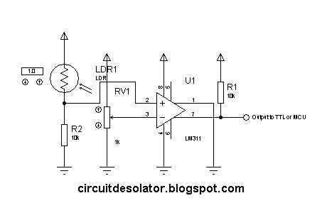
Simple Analog Comparator Circuit using lm311

This is one of the common circuit blocks being used both in digital and analog electronics. Its output is dependent on the relationship of its two input pins. One of the inputs is set to give the reference voltage while the other one is commonly connected to different sensors. If the reference voltage was overcome by the input connected to the sensor, the output of the comparator changes.

In this circuit, the we'll use an LDR.


The advantage of a comparator IC than an opamp used as an comparator is the property of IC comparators to be open collector output. Having this feature, we can set the output of the comparator beyond its biased voltage.

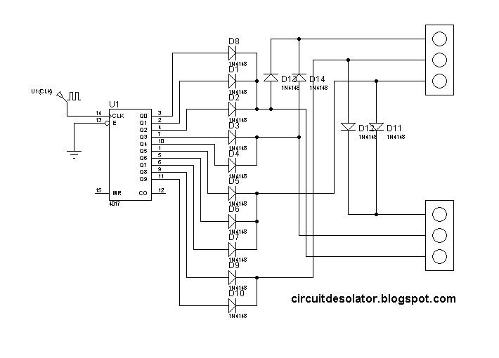
Traffic Light Circuit (based on 4017)

This is a simple design of a traffic light project that uses 4017 IC. This circuit demonstrate a simple two traffic light. 

The clock source is not included in the diagram but you can use 555 astable circuit as an oscillator.

The time of switching of the lights are in proportions.

3/10 for green
2/10 for yellow 
5/10 for stop


In the schematic, a traffic light model was used in the simulation. But in the actual, you can implement it using LEDs.

Here is the schematic of the traffic light circuit:


This is a demo video:


Saturday, January 15, 2011

Latching Relay Circuit

There are situations that we need to implement latching relay action. This can be implemented by connecting the relay pins to proper configuration with respect to the button and the power source. In this blog post, I will present the circuit/schematic and demo video simulation of a latching relay.

Here is the schematic:


The components in this circuit are:

1. 1 latching switch --> serves as the reset
2. 1 normally open switch --> acts as the trigger button
3. 1 diode(1n4001) --> snubber diode against kick voltage
4. 1 spdt 5v relay
5. 1 LED --> serves as the load
6. 1 330 ohm resistor --> current limiting

**The power source is operating in 5volts.

The circuit can also be triggered by logic ICs(TTL/CMOS) using proper interfacing method. I usually use another relay that serve as the trigger button when interfacing ICs to latching relay circuit.

Here is the demo video:


Wednesday, January 12, 2011

Simple Light or Dark Activated Switch Circuit

This is a basic circuit that can be constructed by students.

It uses a transistor as a switch, LDR as the sensor, variable resistor for calibration, diode as a snubber and the relay as the switching component.

Sunday, January 9, 2011

PIC based PS/2 AT Keyboard Decoder

I constructed a simple PIC based PS/2 AT Keyboard Decoder that is frequently used as an input device to different electronic projects.

Thursday, January 6, 2011

Simple utility amplifier (using LM386)

Simple amplifiers are easy to build. Specially if you're using amplifier ICs.

Here is my simple utility amplifier. I used this on project development, etc.

This is not an advisable design but enough if you just want to hear louder sound from you coming input.


Here is the schematic.

Sunday, January 2, 2011

3-bit JK Down Counter Circuit

JK flip-flop is commonly used in different counter circuits.

This is a circuit of a 3-bit JK down counter circuit.

Note that the push button needs a switch debouncer to have a clear count. Click here on how to implement switch debouncer.

Demo video using Proteus Isis 7 (Download proteus here)

Basic led chaser circuit (4017)

This is a simple demo of a led chaser using 4017. It has an enable, reset and cascade pin making it a good choice in logic circuit design.

Please note that the schematic doesn't contain the oscillator circuit and the V+ and GND of 4017 are hidden.


Here is a simulation video of the Led chaser using Proteus Isis 7(Download proteus here)


Saturday, January 1, 2011

Logic Based Digital Queuing System Circuit (74192 counter)

Another common logic circuit project is an electronic queuing system.

This is a simplified design using a up/down counter IC, 74192. It is a versatile logic IC that has a separate pins for up and down count. Also, an RS latch is used for the indicator of the counter number.

Here is the schematic/circuit design.


Please note:
1. Check the V+ and GND of the IC used. They are hidden on the schematic.
2. The seven-segment display needs current limiting resistor.
3. Switch debouncer circuit might be need if switch bounces are present. A reference on switch debouncer(Click Here).


Simulation video using Proteus Isis 7(Download proteus here):


Logic Based Digital Queuing System (74192 counter)

Thursday, December 30, 2010

Digital Clock based on 74ls90

Digital clock never get obsolete on digital electronic projects.

Many approach and design are available online but implementing it using 7490 decade counter is one of the easiest design. This can be proven by looking at its simplicity and compactness.

Check its datasheet to see it's pin configuration and how it's being implemented.

On our digital clock circuit. We will use divide-by 10, divide-by 6 and divide-by 2. This circuit design is not adjustable so you need to start the clock exactly 00:00 or 12am.

here's the circuit of 7490 to be used:

for SECONDS' ones, MINUTES' ones and HOURS' ones are divide by 10.

for SECONDS' tens and MINUTES' tens are divide by 6.

for HOURS' ones is divide by 2.

please refer to the diagram below for the appropriate circuit.


The output of the HOURS' tens digit is connected to an AND gate that will reset the counter to 00 when 12 is counted.

The clock source will depend on the designer. It can be a 60hz from the powerline, 555 astable mode, crystal oscillator or any oscillators.

here's the circuit:


Here's the simulation video using Proteus Isis 7 (Download proteus here):


Up/Down Counter Circuit

Counters are very common experiments on digital electronics subjects.

Here's a simple up/down counter that uses 74190.


This circuit is easy to implement and here are some of its features:

Presettable - having this capability, it is easy to use for down timers with initial value like 24second shot clock.
Parallel output(BCD) - its bcd output can be easily interface to a bcd-to-sevensegment decoders.
Ripple clock output - you can cascade many 74190 to form 2digit, 4digit and Xdigit counters.
Single input pin for up/down - in case that the requirement is to control the count in a single pin, this 74190 is very applicable.

Please note that you need a switch debouncer on the switch so that you can have a clean count..

Reference for switch debouncer.
http://circuitdesolator.blogspot.com/2010/12/switch-debounce-circuit.html


Simple magnitude comparator (7485 IC) Circuit

In designing logic circuit, it is sometimes necessary to compare values of two digital data. In this case, creating your own magnitude comparator can cause you more logic IC and can consume more time and money. This magnitude comparator IC might help you. It can compare two 4-bit data but can be cascaded to other magnitude comparator. It is the 7485 IC.

This 7485 magnitude comparator is one of my favorite logic ICs. This IC helped me a lot in my school projects specially on digital electronic games like chess, fight combat, etc. I usually use this chip in declaring the winner of having a higher score.

Here is a sample circuit.


A demo video of the magnitude comparator simulation using Proteus Isis 7 (Download Proteus here)


Wednesday, December 29, 2010

LED Dot Matrix Pin Configuration (pinouts)

Many students ask about the pin configuration of LED Dot Matrix.

So I posted here the commonly used LED matrix.

 7x5 LED Matrix


 8x5 LED Matrix


 8x8 LED Matrix


Enjoy working on your LED Matrix!

Tuesday, December 28, 2010

Jack en Poy or Rock-paper-scissors using C language

More that a year ago, I've created a C code demonstrating a game called jack en poy(Rock-paper-scissors).
I've written that code since those were the days that I am exploring C programming.

You can download my code here.

Jack en Poy in C